|
|
|
Who's Online
There currently are 5789 guests online. |
|
Categories
|
|
Information
|
|
Featured Product
|
|
|
 |
|
|
There are currently no product reviews.
 ;
THIS MANUAL IS VERY GOOD AND VERY CLEAR
PLEASE NOTE IT DOES NOT CONTAIN THE SETUP INFORMATION TO ALIGHN THE GEARS IN THE CD MECH IT DOES SHOW ALL THE PARTS AND THEIR LOCATIONS .
;
Complete service and operation manual. All schematics are there, all circuit boards AND add-on boards. Including exploded views ,component names and specifications. Also electrical and mechanical adjustment procedures are in this manual. This manual also covers the more advanced BR-S811E unit. Scan quality is fair and usable.
 ;
High quality scan of original Service Manual. Everything´s fine!
;
Good scan of the original service manual. All schematics and adjustment procedures are there. It helped me to fix a long lasting problem with the tracking circuitry. The manual also includes the supplementals 1,2 and 3. Included are; electrical schematic's , pcb layout's, mechanical drawing's and exploded views, disassembly manual and maintenance procedures. 236 pages.
;
The Service Manual received was helpful. The electronic information is exactly what I needed.
I recomend all of my friends about this technical page.
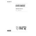
6. ADJUSTMENT PROCEDURE
(1) ALIGNMENT INSTRUCTIONS
EQUIPMENT NEEDEDIMPORTANT AM Signal Generator1.Check power-source voltage. FM Signal Generator2.Set the function switch to band aligned. Oscilloscope3.Keep the function input as low as possible to adjust. VTVM(AC,DC) accurately. Test loop antenna (MW Adjustnent) 4.Modulation and modulation frequency. Dummy antenna(FM Adjustment) Stereo signal modulator. Distortion analyzerModulationModulation Frequency.
MW 2 3 1503KHz Max sensitivity CT01 2 3 100.10MHz Repeat steps 1 and 2 several times. NO STEP 1
FREQUENCY
(3) MW TRACKING ADJUSTMENT
Signal Generator : Connects to the MW Ant. Coil through the loop antenna. Adjust for the indication of VTVM of the wave form of scope to be maximum.
(5) FM MONO DISTORTION ADJUSTMENT
DC VOLTMETER Connect to TP02 (-),TP03 (+) through the chockcoil (100 H). Signal Generator Connect to FM ANT. Jack (FM IN) through thedummy. Distortion Meter Connect to the output.
ADJUSMENT L102
(7) FM/MW TUNED LEVEL ADJUSTMENT
FM Signal Generator : Connect to FM ANT. Jack (FM IN) through the dummy. MW Signal Generator : Connect to MW ANT. Coil thriugh Loop antenna.
ADJUST FOR Max sensitivity
NO 1
FREQUENCY 100.10MHz
ADJUST FOR DC Voltmeter 0V min T.H.D
ADJUSTMENT T101
BAND STEP SIGNAL GENERATOR ADJUST FOR FM 1 2 MW 1 2 100.10MHz 30dB 100.10MHz 30dB 999KHz 80dB 999KHz 80dB TUNED TUNED TUNED TUNED ON OFF ON OFF
ADJUSTMENT VR02 VR02 VR01 VR01
612KHz
T102
Repeat steps 1 and 2 several times
EQUIPMENT NEEDEDIMPORTANT
AM Signal Generator1.Check power-source voltage. FM Signal Generator2.Set the function switch to band aligned. Oscilloscope3.Keep the function input as low as possible to adjust. VTVM(AC,DC) accurately. Test loop antenna (MW Adjustnent) 4.Modulation and modulation frequency.
AM-SG
MHz
AC EVM
OSCILLOSCOPE
FM-SG
MHz OUT
DC EVM
75ohm
UNIT
AM LOOP antenna
60cm OUTPUT terminal
TP12 Chassis TP13
Choke coil 100 H output
MODULATION
MODULATION FREQUENCY
DISTORTION ANALYSER
MW FM
30% 100%(75KHz)
400Hz 400Hz
(2) TUNING FREQUENCY RANGE ADJUSTMENT
(FM) DC VOLTMETER CONNECT TO TEST POINT TP1 and GND (MW) DC VOLTMETER CONNECT TO TEST POINT TP1 and GND
NO 1 2 BAND FREQUENCY FM MW 87.50MHz 522KHz ADJUST FOR 1.5V 1V ADJUSTMENT L4 L103
(4) FM-RF ADJUSTMENT
Signal Generator : Connects to FM ANT. JACK (FM IN) through the dummy.
(6) FM STEREO SEPARATION
PILOT SIGNAL ON ADJUST FOR Different of R and L Must be maximum ADJUSTMENT VR03
NO 1 2
FREQUENCY 90.10MHz
ADJUST FOR Max sensitivity
ADJUSTMENT L1,L2,L3
STEREO OSCILLOSCOPE FM-SG Dummy UNIT
FM IN OUTPUT
Repeat step 1 several times
DC EVM
FM-SG
MHz OUT
AC EVM
OSCILLOSCOPE
EXT
OUT
VTVM VR03
OUT
UNIT FM AM GND TP11 GND UNIT
OUTPUT terminal FM ANT
STEREO MODULATOR
13
14
|
|
|
> |
|