|
|
|
Who's Online
There currently are 6002 guests online. |
|
Categories
|
|
Information
|
|
Featured Product
|
|
|
 |
|
|
There are currently no product reviews.
 ;
I really like this manual and it's reliable.I found and bought easly.thank you.
;
Thank you very much. the Instruction corresponds to my expectations. Sent it in time. I don't regret that paid money.
;
Good quality. Quick service. I recommend to everyone.
;
Very good quality scan of the document. I am very pleased with what I got.
;
PDF Contains
Technical Data, Mechanical data, Detailed Circuit diagram with components value, PCB layout. Actual PCBs Print. Component List, Spare parts code list and Input output detail. It cover LBB1211, LBB1212, LBB1213, LBB1216, LBB1217.
It is the actual Service Manual for SQ10
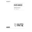
Measurements
IIS CLK11 NMUTE DAC
22 25 AMPLIFIER
1200 -17
1200 -19
CL96532086_062.eps 080999
Figure 8-33 Keep processor 7202 in reset by forcing pin 7 of connector 1208 to +5V. This puts the processor outputs in tristate. Check the reset at pin 4 of processor 7202 to make sure that the processor is in reset. Now, force port 0-4 pin 33 at 7202 to 0V to set the decoder outputs (SCLK, WCLK, DATA, and CL11). Check the MUTE pin 11 at 7309 : this pin should be low. Connect via an I2S generator I2S-signals to the DAC : Pin 1 at 7309: SLCK. Pin 2 at 7309: WCLK. Pin 3 at 7309: DATA. Connect also the SYSCLK pin 6 at position 7309 to a clock signal of 11.2896 MHz ±100ppm. Generate an I2S signal equivalent with a sine wave of 1kHz at 0dB for both left and right channels. Check if 0.8 VRMS at pins 14 and 16 at location 7209 with a DC of 1.65VDC. Check if 1.7 VRMS ±2 dB at connector pins 1and 3 at location 1209. Force MUTE Pin 11 at 7309 high. Measure again at pins 1 and 3 at location 1209 : both signals should be at -90 dB.
31
|
|
|
> |
|